QSXM Solder-Down System-on-Module
NXP i.MX 8M Mini 1.6 GHz Quad Cortex®-A53 |
|
2GB LPDDR4, 4GB eMMC |
|
-25 °C to 85 °C |
|
29 x 29 x 2.6 mm |
|
Datasheet |
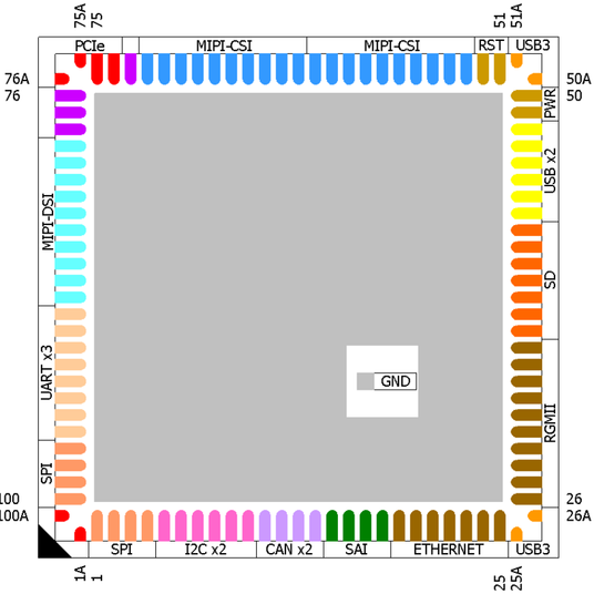
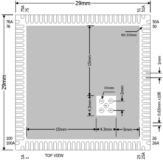
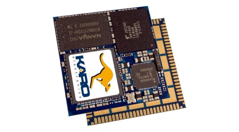
The QSXM is a QFN Style Solder-Down Computer On Module. The module with a small square size of 29mm and a height of 2.6 mm is single-sided assembled. Its QFN type lead style has a 1mm pitch with 108 pads. The ground pad additionally acts as thermal pad.
QS-Standard

Benefit by using QS module family
The QS module family has very compact dimensions. They include a complete embedded System on Module with processor, PMIC, RAM and flash memory.
Because of the very dense packaging on the top side, there are no components on the bottom side of the module, cut-outs on the base board not required. The pin compatible family concept provides all important interfaces needed for embedded designs, e.g., USB, Gigabit-Ethernet, display and many serial interfaces.

Flexibility, high performance and easy integration
All signal connections located at the module edges, allowing easy optical inspection during production. The modules can be assembled by automatic pick & place machines without any mechanical assembly work necessary.
The pin-optimized QS concept enables the use of a simple, cost-effective 2-layer base board.
A development kit with schematics and bill of materials is available to support a quick evaluation and project start.

QSX vs. QS
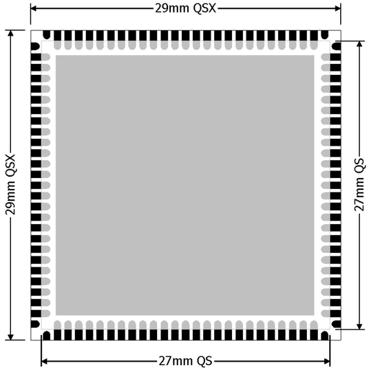
- QSX is a QS module enlarged by 1 mm all around.
- The size hereby increased from 27 mm square to 29 mm square.
- In each corner this gives additional space for a total of 8 further pads which are used for PCIe and USB3.
- The inner 27 mm x 27 mm QS area remains identical, providing full compatibility.
-
![]()
i.MX 8M Mini applications processor
The i.MX 8M Mini applications processor blends advanced processing capabilities with sophisticated audio, video, and graphics to deliver low-power and high-performing solutions for embedded consumer and industrial applications.
-
Assembly of QS-Modules
-
QSXM at a glance
- Main CPU
4 x Cortex-A53, 1.6 GHz
- MCU
Cortex-M4F
- Memory
2GB 32-bit LPDDR4
4GB eMMC- GPU
1 x GCNanoUltra 3D (1 shader) OpenGL ® ES 2.0, 1x GC328 2D - Security
HAB secure boot, TrustZone, True RNG, RSA up to 4096, AES-128/192/256, 3DES, ARC4, MD-5, SHA up to 256, ECC, secure JTAG - Camera
MIPI CSI (4-lanes)
- Display
MIPI DSI (4-lanes)
- Video Decode
1080p60 H.265, H.264, VP9, VP8
- Video Encode
1080p60 H.264, VP8
- Expansion I/O
USB with PHY
- Network/Storage
GbE, SD/eMMC
- IO
4x UART, 4x I2C,
3x SPI, 4x PWM, SAI -
![]()
Processor features
TARGET APPLICATIONS
- General purpose human machine interface (HMI) solutions enabling touch, voice, graphics, video, image analytics and vision
- Streaming video devices – two-way video conferencing, video doorbell and surveillance, digital signage, machine visual inspection
- Streaming audio devices – surround sound, wireless or networked speakers, soundbars, audio/video (AV) receivers, public address systems
- Voice control and voice assistants, with reference designs for homes or noisy industrial environments
- General purpose human machine interface (HMI) solutions enabling touch, voice, graphics, video, image analytics and vision
-
Solder-down SoM
Solder-Down
System-on-Module
Simplifies Design & Production
A SoM, one step above an SoC, incorporates connectivity, multimedia and display, GPIO, operating system, and others in a single module. Although the industry has been traditionally using SODIMM modules (such as push-connector modules, small outline dual in-line memory module), soldered SoM modules are rapidly gaining ground. Solder modules are less expensive than their SODIMM counterparts because they are easier to manage, test in production, and allow for better economies of scale.
SoM-based designs are usually scalable to achieve a fully customized electronics assembly in terms of interfaces and form factors. SoMs can be replaced or upgraded within a carrier board. Some advantages of the SoM approach over an SoC development include cost savings, reduced market risk, reduced customer design requirements, and footprint. The only limitation with an SoM, when compared to the ground-up SoC design, is that there are fewer pins in an SoM.
-
Solder modules can be used just like any other component
Hardware and software integration of the newest 64-bit ARM-processor is becoming increasingly more sophisticated. Integrating everything on a single board can create some engineering challenges. Once a fully custom SoC-based board is built, it can’t be modified without delay and expense. That’s why it’s vital to know what its destination is before you design it. Despite this precaution, porting Linux or another OS to the custom hardware is an onerous task. To overcome this limitation, a SoM offers much more flexibility as the porting is already done. To further reduce costs, most projects are turning to module-based systems to increase time available for application development, reduce complexity and allow designers to focus on their core competencies.
Solder modules can be used just like any other component, and do not need to be handled and inserted manually like a SODIMM. With increasing demands on miniaturization, a SODIMM module requires more space and this can be important. The smallest soldered modules are only 27mm2 (1.1″) and this is the smallest space on which it is physically possible to mount the basic components.
In all types of designs, the connector has its cost. Even a SODIMM200 connector can cost a couple of dollars and push-fit connectors can cost a lot more. Soldering offers considerable strength and therefore the components are less vulnerable to shock and vibration.
The solder-down module’s integral ground plane provides a defined return path, avoiding ground loops and allowing efficient routing of tracks with low EMI. High-speed differential signals can be easily routed on a single layer. The ground plane also aids heat transmission to the baseboard, reducing the need for heat sinks.
In projects with BGA solutions, designers might face various problems. BGAs are very good for density, but they need high precision and it can only be inspected by through x-ray. SoMs in contact with the edges prove to be a better solution as it is possible to visually inspect the connections.
Pre-programmed
All modules will be shipped with a pre-programmed bootloader by default. To speed up the production process, the modules can also be pre-programmed to customer specifications. JEDEC version 5.0 introduces “Production State Awareness” to help avoid possible data corruption during soldering. Only a predefined part of the whole device’s available space can be supported by this feature.
Development Kits
-
![]()
QSXM QSBASE3 Evalkit
Linux is pre-installed and ready for application development. Other features include:
- QS module: QSXM/MM6C/2GS/4GF/E85
- Gb Ethernet
- MIPI Display Connector
- MIPI Camera Connectors
- USB
- M.2 PCIe socket
- 6-layer PCB
Part number: QSXM-SV01
-
![]()
QSXM on Raspberry Pi Touchscreen
The QSXM EvalKit can be mounted directly to the official Raspberry Pi 7inch Touch screen.
- Touch Display works with our QSBASE3 out of the Box.
- Sources available in our Yocto Layer.
-
![]()
QSBASE4 Evalkit
Linux pre-installed and ready for application development. Other features include:
- QS module on sockets
- Gb Ethernet
- MIPI Display Connector
- Two port USB hub, type A connectors
- USB client & power supply, type C connector
- USB to UART bridge, micro-B connector
- 4-layer PCB
-
![]()
QSBASE4 on Raspberry Pi Touchscreen
The QSBASE4 EvalKit can be mounted directly to the official Raspberry Pi 7 inch Touch screen.
- Touch Display works out of the Box.
- Sources available in our Yocto Layer.
Variants
-
An overview of the current standard variants.
Customized versions on request.
-
Part Number QSXM-MM60 Part Name QSXM/MM6C/2GS/4GF/E85 Processor NXP i.MX8M Mini Quad 1.6 GHz SDRAM 2 GiB Flash 4 GB Display-IF MIPI Temperature -25 °C to 85 °C
Product comparison
| TX | QS | Silicon Vendor | SOC | Core | # | Clock | Grade | L2-Cache | I-Cache | D-Cache | Emb. SRAM | NEON | VFP |
|---|---|---|---|---|---|---|---|---|---|---|---|---|---|
| TX93 | QS93 | NXP | i.MX 93 |
Cortex®-A55 Cortex®-M33 |
2 1 |
1.5 GHz |
Ind. | 64 KB | 32 KB | 32 KB | 640 KB | √ | √ |
| TXRZ | QSRZ | RENESAS | RZ/G2L |
Cortex®-A55 Cortex®-M33 |
2 1 |
1.2 GHz 200 MHz |
Ind. | 256 KB (L3) | 32 KB | 32 KB | 128 KB | √ | √ |
| TX8P | QSXP | NXP | i.MX8M Plus | Cortex®-A53 | 4 | 1.6 GHz | Ind. | 512 KB | 32 KB | 32 KB | 256 KB | √ | √ |
| TX8M | QS8M | QSXM | NXP | i.MX8M Mini |
Cortex®-A53 Cortex®-M7 |
4 1 |
1.6 GHz 750 MHz |
Ind. | 512 KB | 32 KB | 32 KB | 256 KB | √ | √ |
| TX8M | QS8M | NXP | i.MX8M Nano | Cortex®-A53 | 2 | 1.4 GHz | Ind. | 512 KB | 32 KB | 32 KB | 256 KB | √ | √ |
| TX6QP | NXP | i.MX6QuadPlus | Cortex®-A9 | 4 | 800 MHz | Ind. | 1 MB | 32 KB | 32 KB | 256 KB | √ | - | |
| TX6Q | NXP | i.MX6Quad | Cortex®-A9 | 4 | 1 GHz | Com. | 1 MB | 32 KB | 32 KB | 256 KB | √ | - | |
| TX6DL | NXP | i.MX6DualLite | Cortex®-A9 | 2 | 800 MHz | Ind. | 512 KB | 32 KB | 32 KB | 128 KB | √ | - | |
| TX6S | NXP | i.MX6Solo | Cortex®-A9 | 1 | 800 MHz | Ind. | 512 KB | 32 KB | 32 KB | 128 KB | √ | - | |
| TX6UL | NXP | i.MX6UltraLite | Cortex®-A7 | 1 | 528 MHz | Ind. | 128 KB | 32 KB | 32 KB | 128 KB | √ | - | |
| TXMP | QSMP | STMicroelectronics | STM32MP1 |
Cortex®-A7 Cortex®-M4 |
1-2 1 |
650 MHz 209 MHz |
Ind. | 256 KB | 32 KB | 32 KB | 708 KB | √ | √ |
| TXMP2 | STMicroelectronics | STM32MP255 | Cortex®️-A35 Cortex®️-M33 |
2 1 |
1.5 GHz 400 MHz |
Ind. | 256 KB | 32 KB | 32 KB | 640 KB | √ | √ |
| TX | QS | NPU | ISP | Graphics Acceleration | Video Codec | Camera Interface | LCD Interface |
|---|---|---|---|---|---|---|---|
| TX93 | QS93 | √ | - | √ (Blending/Composition, Resize, Color Space Conversion) | - | √ | LVDS |
| TXRZ | QSRZ | - | - | √ | √ | √ (TXRZ) / - (QSRZ) | 24bit and MIPI |
| TX8P | √ | √ | √ | √ | √ | LVDS + MIPI + HDMI | |
| QSXP | √ | √ | √ | √ | √ | MIPI | |
| TX8M | QS8M | QSXM | - | - | √ | √ (8M Mini) / - (8M Nano) | √ | MIPI |
| TX8M | - | - | √ | √ | √ | LVDS | |
| TX6 | - | - | √ | √ | √ | 24bit or LVDS | |
| TXUL | - | - | - | - | √ | 24bit | |
| QSMP | - | - | - | - | √ | 24bit | |
| TXMP | QSMP | - | - | √ | - | √ | 24bit and MIPI |
| TXMP2 | √ (1.35 TOPS) | - | √ (OpenGL ES 3.1, Vulkan 1.1, OpenCL 1.2, OpenVX 1.1) | √ (1080p60 encode/decode) | √ (MIPI-CSI 2-lane) | RGB |
| TX | QS | RAM Size | RAM Type | RAM width | ROM Size | ROM Type |
|---|---|---|---|---|---|---|
| TX93 | QS93 | 1 GB | LPDDR4 | 16 bit | 4 GB | eMMC |
| TXRZ | QSRZ | 512MB / 1 GB | DDR3L-1333 | 16 bit | 4 GB | eMMC |
| TX8P | QSXP | 2 GB | LPDDR4 | 32 bit | 8 GB | eMMC |
| QSXM | 2 GB | LPDDR4 | 32 bit | 4 GB | eMMC | |
| TX8M - MINI | 1 GB / 2 GB | DDR3-1600 | 32 bit | 4 GB | eMMC | |
| TX8M - NANO | 512 MB | DDR3-1600 | 16 bit | 4 GB | eMMC | |
| QS8M | 512MB / 1 GB | DDR3-1600 | 16 bit | 4 GB | eMMC | |
| TX6QP | 2 GB | DDR3-1066 | 64 bit | 4 GB | eMMC | |
| TX6Q | 1 GB | DDR3-1066 | 64 bit | 128 MB / 8 GB | SLC NAND / eMMC | |
| TX6DL | 1 GB | DDR3-800 | 64 bit | 128 MB / 4 GB | SLC NAND / eMMC | |
| TX6S | 256 MB / 512 MB | DDR3-800 | 16 bit / 32 bit | 128 MB / 4 GB | SLC NAND / eMMC | |
| TX6UL | 256 MB | DDR3-800 | 16 bit | 128 MB / 4 GB | SLC NAND / eMMC | |
| TXMP | QSMP | 256 MB / 512 MB | DDR3-1066 | 16 bit | 128 MB / 4 GB | SLC NAND / eMMC |
| TXMP2 | 1 GB | LPDDR4 | 16 bit | 4 GB | eMMC |
| USB | Ethernet | UART | I2C | SPI | SD / MMC | Serial Audio | CAN | SATA | External Memory Interface | |
|---|---|---|---|---|---|---|---|---|---|---|
| TX93 | 2 | 2 | 8 | √ | √ | 1 | 2 | 2 | - | - |
| QS93 | 2 | 2 | 5 | √ | √ | 1 | 1 | 2 | - | - |
| TXRZ | 2 | 2 | 7 | √ | √ | 1 | 2 | 2 | - | - |
| QSRZ | 2 | 1 | 4 | √ | √ | 1 | 1 | 2 | - | - |
| TX8P | 2 | 2 | 4 | √ | √ | 2 | 4 | 2 | - | PCIe |
| TX8M | 2 / 1 | 1 | 4 | √ | √ | 2 | 4 | - | - | PCIe |
| QS8M | 2 / 1 | 1 | 4 | √ | √ | 1 | 1 | - | - | - |
| QSXM | 2 | 1 | 4 | √ | √ | 1 | 1 | - | - | PCIe |
| QSXP | 2 | 1 | 4 | √ | √ | 1 | 1 | 2 | - | PCIe |
| TX6QP | 2 | 1 | 5 | √ | √ | 2 | 2 | 2 | √ | 16 bit / PCIe |
| TX6Q | 2 | 1 | 5 | √ | √ | 2 | 2 | 2 | √ | 16 bit / PCIe |
| TX6DL | 2 | 1 | 5 | √ | √ | 2 | 2 | 2 | - | 16 bit / PCIe |
| TX6S | 2 | 1 | 5 | √ | √ | 2 | 2 | 2 | - | 16 bit / PCIe |
| TX6UL | 2 | 2 | 8 | √ | √ | 2 | 1 | 2 | - | - |
| TXMP | 2 | 1 | 8 | √ | √ | 1 | 1 | 2 | - | - |
| TXMP2 | 2 | 2 | up to 9 | 8 | 8 | 1 | √ | 3 | - | - |
| QSMP | 2 | 1 | 7 | √ | √ | 1 | 1 | 2 | - | - |
| Supply Voltage | U-Boot [mW] | Linux [mW] | Sleep [mW] | |
|---|---|---|---|---|
| TX93-5210 | 5V / 3.3V | 1110 / 1025 | 725 / 655 | 150 / 125 |
| QSRZ-G2L0 | 3.3V | 782 | 657 | 500 [1] |
| TXRZ-G2L0 | 5V / 3.3V | 1040 / 941 | 960/ 871 | 985 / 900 [1] |
| TX8P-ML81 | 5V / 3.3V | 1900 / 1800 | 1685/ 1600 | 115 / 100 |
| TX8M-1610 | 5V / 3.3V | 1110 / 1110 | 900 / 880 | 130 / 120 |
| TX8M-1620 | 5V / 3.3V | 1275 / 1277 | 1055 / 1059 | 260 / 244 |
| TX8M-ND00 | 5V / 3.3V | 860 / 845 | 670 / 650 | 85 / 80 |
| TX6Q-8037 | 5V | 2400 | 850 | 180 |
| TX6Q-1030 | 5V / 3.3V | 2125 / 2015 | 800 / 760 | 80 / 80 |
| TX6U-8033 | 5V / 3.3V | 1925 / 1840 | 800 / 760 | 80 / 80 |
| TX6S-8034 | 5V / 3.3V | 1425 / 1310 | 550 / 530 | 80 / 80 |
| TXUL-5010 | 5V / 3.3V | 710 / 620 | 550 / 460 | 29 / 28 |
| TXUL-5011 | 5V / 3.3V | 760 / 650 | 550 / 460 | 29 / 22 |
| TXUL-8013 | 5V / 3.3V | 775 / 675 | 365 / 340 | 100 / 76 |
| TXMP-1570 | 5V / 3.3V | 875 / 775 | 800 / 695 | 60 / 45 |
| QSMP-1570 | 3.3V | 660 | 560 | 20 |
| QSMP-1530 | 3.3V | 620 | 520 | 15 |
| QS8M-MQ00 | 3.3V | 840 | 510 | 60 |
| QS8M-ND00 | 3.3V | 670 | 500 | 45 |
| QSXM-MM60 | 3.3V | 1161 | 739 | 40 |
| QSXP-ML81 | 3.3V | 1520 | 1230 | 86 |
[1] Renesas RZ/G2L has no different power domains, voltages cannot be switched off and DRAM self-refresh is not supported.
| glmark2 score | CoreMark | DhryStone |
Whetstone [MIPS] |
Memcpy [MB/s] |
Memset [MB/s] |
STREAM copy [MB/s] |
STREAM scale [MB/s] |
STREAM add [MB/s] |
STREAM triad [MB/s] |
|
|---|---|---|---|---|---|---|---|---|---|---|
| TX93-5210 | - | 12762 | 9330534 | 32258 | 2657 | 4725 | 5738 | 3307 | 4230 | 4239 |
| QSMP-1570 | 74 | 3788 | 2199518 | 10204 | 620 | 1437 | 1345 | 794 | 705 | 584 |
| QS8M-ND00 | 192 | 9222 | 6922571 | 24390 | 372 | 1228 | 808 | 814 | 710 | 677 |
| TXRZ-G2L0 | 212 | 8853 | 6850488 | 22727 | 1095 | 2322 | 2358 | 2286 | 2363 | 2377 |
| QS8M-MQ00 | 280 | 21075 | 7912644 | 27777 |
1132 |
2830 | 2570 | 2647 | 2341 | 2004 |
| QSXM-MM60 | 361 | 21028 | 7912644 | 27777 | 1885 | 8533 | 4243 | 2950 | 2716 | 2301 |
| QSXP-ML81 | 863 | 21104 | 7912957 | 27777 | 2008 | 10690 | 4673 | 2910 | 2617 | 2216 |
| W | L | T | |
|---|---|---|---|
| TX6 | 31mm (1.2'') | 67.6mm (2.7") | 4mm (0.16") |
| TX8M-LVDS | 28mm (1.1") | 67.6mm (2.7") | 4mm (0.16") |
| TX93 | TXUL | TXMP | TX8M-MIPI | TX8P | TXRZ | 26mm (1.0") | 67.6mm (2.7") | 4mm (0.16") |
| QS93 | QSMP | QS8M | QSRZ | 27mm (1.05") | 27mm (1.05") | 2.3mm (0.09") |
| QSXM | QSXP | 29mm (1.14") | 29mm (1.14") | 2.3mm (0.1") |
| TXMP2 | 26mm (1.0") | 67.6mm (2.7") | 4mm (0.16") |


